
When I got my first multicopter (the Eachine EB185), a very simple charger came as part of the package. As drones and such fascinated me more and more, I felt I had to get a mores professional charger. In my opinion, separating the power supply and the charger offers more flexibility and also opens up the possibility for cheap home build power supply solutions – so this is the route I took.
Most self made power supplies are based on PSUs taken from desktop computers or even servers. While this will give you a quite powerful and reliable solution, it also requires some basic electronic skills. You have to do some things in the PSU to ensure power output in spite of having no computer components drawing juice from the unit. This was something I felt not up to.
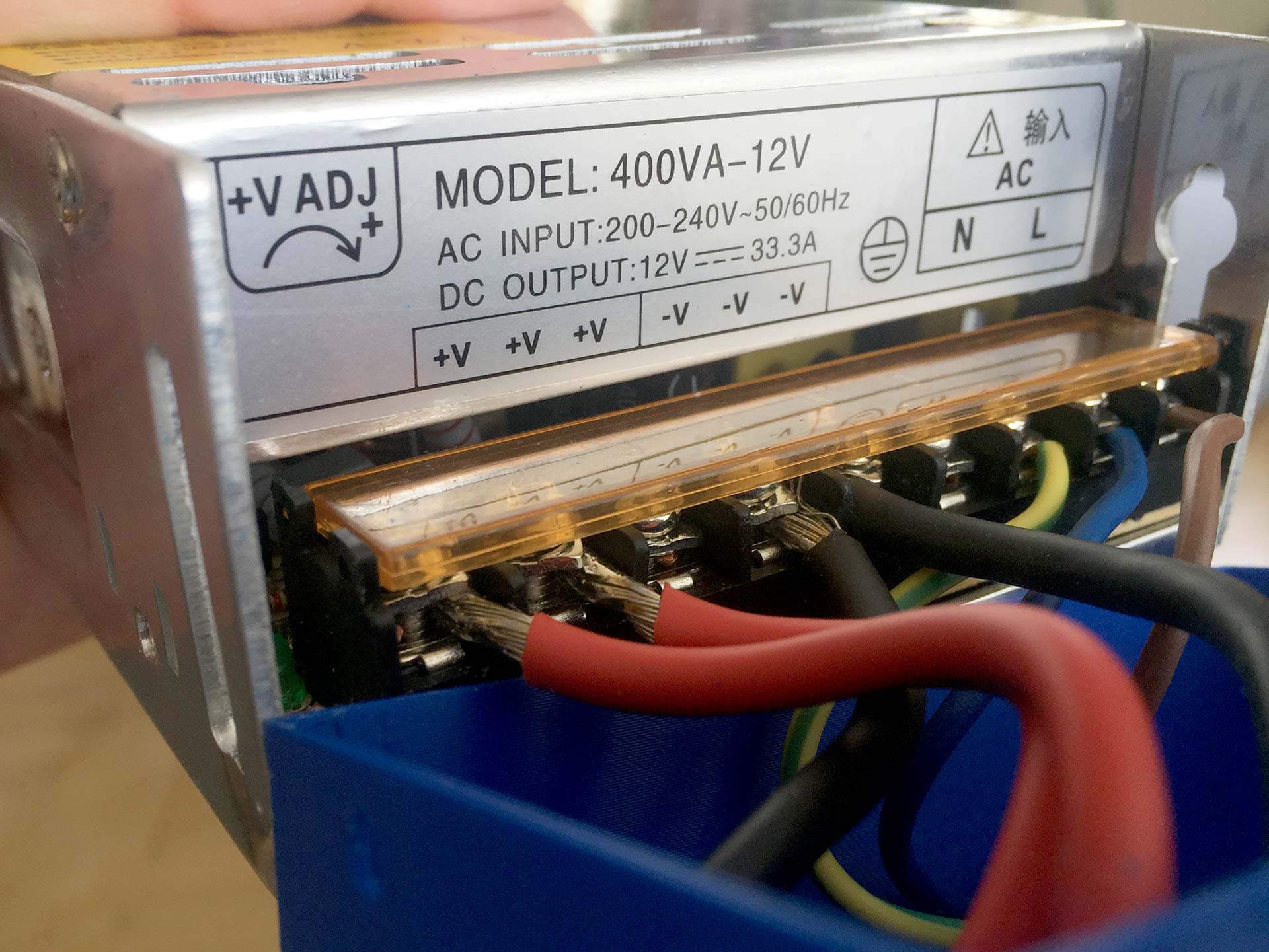
With some further researching, I stumbled upon this really helpful article in a German forum. Andi – the guy who wrote this – turned a 400 W / 12 V LED power supply into a power supply for his charger.
I very much followed his guide, except I did not go to such length as to swap out the fan unit and I used a 3D printer to built the housing for the additional components instead of using aluminium sheeting.
In order to be flexible with regards to connectivity, I installed a set of 4mm banana connectors and an XT60.
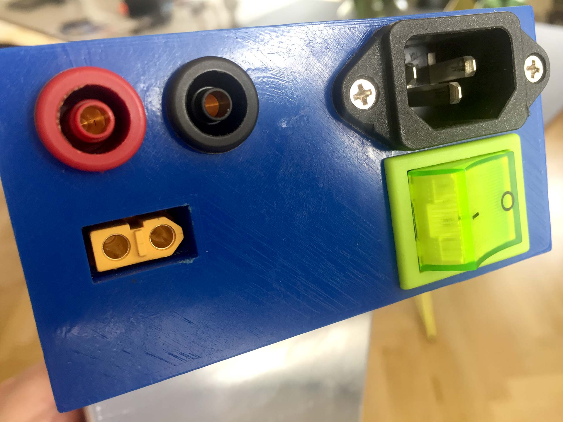

Instructions: building a LiPo charger power supply from a LED power supply
Materials needed
- an LED power supply (will be 12V and should have enough watts for your needs, I used this one from ebay)

- the 3D printed power supply endcap
- XT60 female connector (it’s always good to have a few of them lying around…)
- 2x 4mm banana plug connectors (1 black, 1 red if you want to go with the standard)
- red and black silicon wire for the DC wiring (I used 4 mm² which made the wiring quite stiff and a bit difficult to install)
- 240 V connector (I used a 3 pole Kaltgerätestecker, salvaged from a computer PSU)
- 240 V on/off switch (salvaged from the above computer PSU)
- wires for 240 V wiring (brown, blue, green/yellow according to standards here in Germany)
- heat shrink tubes
Tools needed
- 3D printer (you don’t have to have one yourself – ask a friend or find a makerspace nearby)
- wire cutters
- screw driver
- soldering iron (this needs to have a high wattage – otherwise it’ll take you ages to solder the big wires)
- multimeter
Step by step instructions
1. Measure your power supply, 240 V plug and switch and adapt the 3D model to match your items.
There should be no need to measure the XT60 and banana plug sockets, as they are standardized, but feel free to double-check that if you want to be extra sure.
2. Print the 3D model and check the fit of everything.

3. Connect (i.e. solder) and mount the AC parts. Isolate the connections with heat shrink tube. I recommend, you do as much of the soldering as possible before installing the plug and switch. But pay attention: some wires can only be connected after the parts are installed in the housing. Once you are finished, you should have three wires (phase, ground and neutral) left, waiting to be connected to the power supply.
4. Connect and mount the DC parts. Use the heat shrink tube for isolation. Use dedicated cables for the banana plugs and the two ports of XT60 connector. This leaves you with 4 more wires (2 positive, 2 negative).
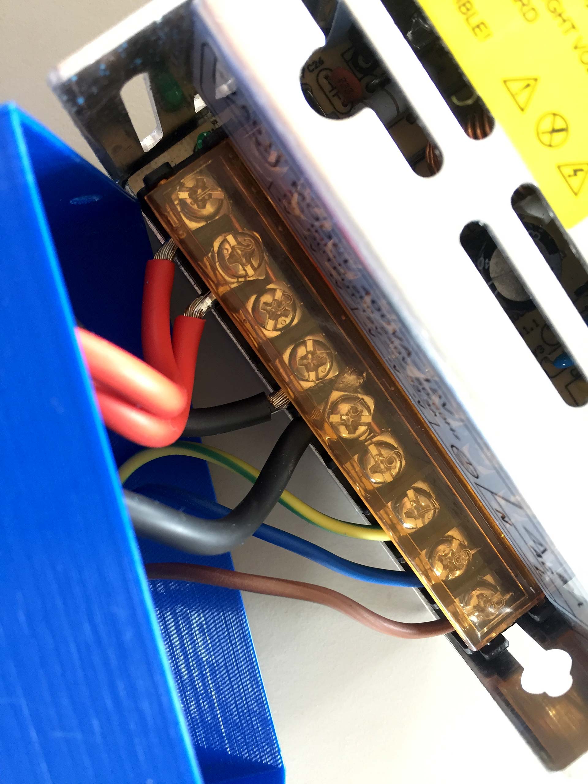
5. Now, you need to hook up the wires to the terminal in the power supply. My power supply came with 3 terminals for negative and 3 for positive connections. In order to reach a more even distribution on the circuit board, I first connected all 3 positive terminals with one another, using a copper wire. I did the same with the 3 negative terminals.
Then, finally, hook up the DC and AC wires.
6. Check all connections for possible shorts with the multimeter. Everything must be properly isolated as you are now going to push everything into the 3D endcap.
7. Push the endcap onto the power supply, guide the cables into a good position by bending and pushing them a little. Once the endcap is in place, fasten it with screws (or use some gaffer tape).
This is it. Connect your LiPo charger with an XT60 or banana plug cable and start charging!
As usual, please send me your feedback – if there is anything that I can improve, I will try to do just that.
Sources
- Andi’s article on converting a LED power supply (German)
- How to choose LiPo battery charger & power supply by Oscar Liang